| Document/Purpose | IRD IOR Capable Chaser (ICAC)/SV ↔︎ IOR Cooperative Target (ICOT) |
| Traceability (Upstream /Downstream) Documents | Upstream: 1.8 Boundaries and Interfaces Downstream: ICD |
| Status | DRAFT – Ready for Review |
| Baseline Version/Date Current Version | Not yet established | v0.1 |
| Last Updated | |
| Owner / Lead | Sanjay Chadha |
| Contributors | |
| Reviewers | |
| Scope/Out-Of-Scope | Scope: IRD content Out-of-Scope: ICD |
Table of Contents
- What and Why of In-Orbit Refueling (IOR)
- Objective of the IOR Initiative
- Objective of this Document
- Scope
- Relationship to Other Work
- IOR Architecture
- Standardized External IOR Interfaces
- IOR Components, Capability and Authority
- IOR Spacecraft Capability Levels
- IOR Spacecraft Capability Level Requirements
- IOR Enabled Capability Requirements
- IOR Aware Capability Requirements
- IOR Cooperative Capability Requirements
- IOR Capable Capability Requirements
- Ground Segment (GS) Connectivity and Autonomy
- Autonomy Requirements
- Local Connectivity between Spacecraft
- Authority and Control
- Lifecycle CONOPS
- Service Supply
- Propellant Transfer
- Interaction Flow
- Spacecraft Classification
- Spacecraft State
- RPOD State
- Spacecraft Relative Nav Info
- Spacecraft Return Plan
- IOR Refuel Service Plan
- Abort Command
- Data Structures
- Refuel Service Request
- RPOD Related Terms (Adapted from IRSIS & CONFERS)
- Industry Terms and Definitions
- Acronyms
Introduction
What and Why of In-Orbit Refueling (IOR)
Space is becoming the decisive strategic domain for both economic prosperity and national security. The survivability and maneuverability of defense constellations, and the scalability of commercial satellite fleets, are still fundamentally constrained by finite onboard fuel.
In-orbit refueling (IOR) is the missing capability that enables both military agility and commercial sustainability. Without scalable in-orbit servicing and refueling, space becomes more congested, more vulnerable and less investable.
In‑orbit refueling is the process of transferring propellant between spacecraft while they are already in space, rather than launching fully fueled vehicles from Earth. It enables satellites, space tugs, and deep‑space missions to extend their operational life or reach more ambitious destinations. This capability reduces launch mass, lowers mission cost, and supports long‑term infrastructure like lunar or Mars transport systems.
Objective of the IOR Initiative
For IOR to become viable at scale, service providers, constellation operators, and satellite manufacturers must work together within an interoperable framework.
With this objective, the In-Orbit Refueling Initiative was started. It builds on efforts from CONFERS and IRSIS and applies systems engineering practices to define interfaces and verification methods that enable and confirm cooperation among stakeholders.
Objective of this Document
This is an IRD document for interface between two spacecrafts being part of the IOR system.
Scope
This document defines the interface requirements for inter-spacecraft communication between the IOR Capable Chaser (ICAC / Service Vehicle) and the IOR Cooperative Target (ICOT) during in-orbit refueling operations.
Relationship to Other Work
This initiative builds on and extends prior work from CONFERS and IRSIS.
CONFERS and IRSIS have established:
- High-level concepts of operations (CONOPS) for on-orbit servicing and refueling
- Guidelines for cooperation, safety, and servicing interactions
- Initial definitions of servicing roles and interaction principles
This initiative extends prior work by developing the CONOPS, mission context, mission requirements, system requirements, and interface definitions needed for end-to-end IOR service delivery, and organizing them in a traceable systems engineering framework that supports implementation readiness. It further establishes an end-to-end QA and compliance framework, including validation, verification, and certification mechanisms, to ensure interoperable and reliable system integration across the IOR ecosystem.
Specifically, this initiative:
- Defines explicit interface requirements (IRD) between system components, enabling practical interoperability
- Identifies and structures interfaces across the full IOR ecosystem, including spacecraft, ground systems, and communication layers
- Introduces capability-based cooperation levels, enabling standardized classification of spacecraft participation
- Bridges the gap between CONOPS and implementation by providing interface definitions that can be directly used by engineering teams
- Enables modular ecosystem development, allowing multiple commercial entities to independently develop compatible components
- Expands the scope beyond spacecraft interaction to include connectivity, autonomy, and operational constraints, required for real-world deployment
This work provides a holistic systems view of IOR, enabling:
- Standardized interaction across heterogeneous systems
- Scalable commercial participation
- Reduced integration complexity across providers
In summary, while CONFERS and IRSIS define how IOR should operate, this initiative defines how systems must interface to make it operationally and commercially viable.
IOR System Overview
IOR Architecture
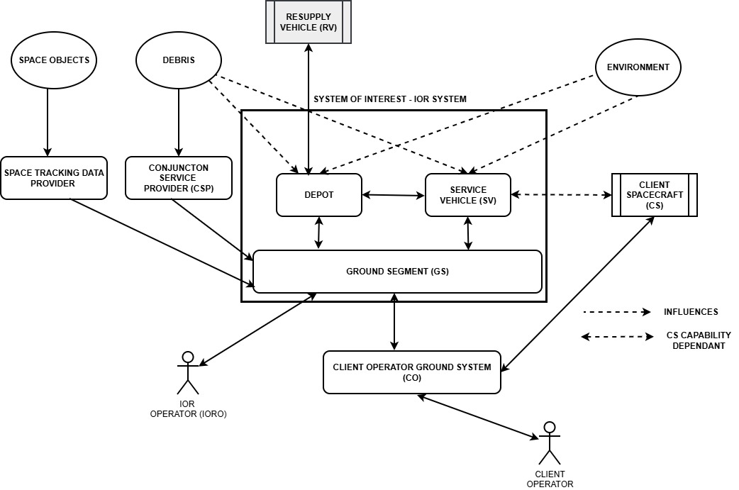
The IOR system includes the following Operational entities:
- Supplier Ground Segment – Provides mission planning, command, and monitoring functions for IOR operations and client coordination
- Depot (D)
- Service Vehicle (SV)
- Client Operator GS – Client is involved in the delivery process
- Client Spacecraft (CS)
- Launch Vehicle (LV)
- Resupply Vehicle (RV)
- Resupply Ground Segment
- Space Traffic Management (STM)
- Space Tracking Data Provider (SPDP_
- Conjunction Service Provider (CSP
- Space Environment – includes orbital dynamics, drag, gravity, debris, sun, radiation, thermal effects, temperature,
Standardized External IOR Interfaces
With the objective of creating a truly common IOR framework, this initiative defines standardized interfaces for:
- Inter-Spacecraft Interfaces
- Physical (Docking/Transfer) – These are the two SERB-approved physical interfaces.
- Proximity Operations and Relative Navigation – Defines how two spacecrafts interact across three supported capability levels: IOR Enabled, IOR Aware, and IOR Cooperative. Definitions are provided in Appendix: 1.11.0: Terminology and Definitions.
- Inter-Ground System Interfaces
- IOR Service Provider <-> Client Operator Ground Systems– Defines how the service provider and client operator coordinates planning, authorization, and execution of services.
- IOR Service Provider <-> Resupply Provider– Supports resupply providers to coordinate and deliver propellant to the service provider in a standardized manner.
- Ground Systems to Spacecraft Interfaces
- IOR Service Provider Ground System <-> Service Vehicle/Depot – Supports command, mission planning, and execution of servicing operations.
- Client Operator Ground System <-> IOR Cooperative Client Spacecraft – Provides telemetry, health monitoring, and coordination support for servicing activities to IOR System
These interfaces are intended to enable companies to develop compliant components and participate in a shared IOR ecosystem.
IOR Components, Capability and Authority
IOR Spacecraft Capability Levels
This initiative defines 4 level of cooperation capability levels for space crafts: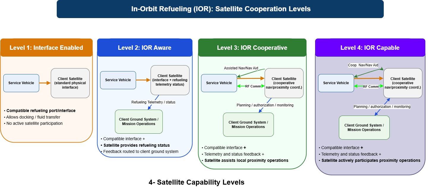
- Interface Enabled Satellite provides a compatible physical refueling interface allowing propellant transfer but does not actively participate in refueling operations.
- IOR Aware In addition to the physical interface, the satellite provides telemetry feedback to its ground system indicating refueling status and progress. IOR Aware must provide following controlled by Ground System:
- Delivers Realtime telemetry data
- Delivers RPOD status (including dock complete),
- Provide propellant levels in real time
- Perform attitude control
- Able to perform pitch roll and yaw on commands from the GS.
- IOR Cooperative – In this level the target assists the chaser in the RPOD operations, specifically the pre-docking, docking, undocking and post docking operations. In this level satellite assists the chaser assisting proximity operations through local attitude alignment support. The satellite must be capable of performing these functions autonomously and locally:
- Local communication based on protocol defined by this initiative.
- Execute Perform pitch roll and yaw in cooperation with SV
- Perform attitude control
- Provide propellant status feedback
- IOR Capable – IOR capable spacecrafts are able to perform the IOR functionality as a chaser and fully cooperate with IOR capable as a target. Service Vehicle, Depot and Resupply Vehicle must be IOR capable. As a chaser the spacecraft leads the RPOD process as a master and as a a target spacecraft fully cooperates as a slave. This initiative defines how to IOR capable spacecrafts interact in a standard compliant manner.
Each IOR capability level is strictly defined. All features must be met to be classified at a given capability level.
IOR Spacecraft Capability Level Requirements
Four levels of spacecraft capability are defined, with more details here. These capabilities define the minimum requirements for an entity to be classified as IOR Enabled, IOR Aware, IOR Cooperative and IOR Capable within this initiative.
The Depot, Service Vehicle (SV), Resupply Vehicle (RV), and IOR Capable Client Spacecraft (CS) share IOR Capable as a common set of capability level – enabling cooperative proximity operations and refueling.
IOR Enabled Capability Requirements
Physical Interface
These are Physical Interfaces between SV, Depot, Client Craft and Resupply Vehicle.
Space System Command’s System Engineering Review Board (SERB) has two approved standard interfaces for satellite refueling –
- Northrop Grumman’s Passive Refueling Module (PRM) and
- Orbit Fab’s Rapidly Attachable Fluid Transfer Interface (RAFTI).
Industry solutions for refueling of National Security Space assets equipped with these SERB-approved interfaces are sought to meet sustained space maneuver (SSM) needs by 2030
IOR Aware Capability Requirements
Autonomy
- Must be able to operate in autonomous mode with guidance from Ground Station
- Must accept only abort/override commands from Ground Station during autonomous operations
Ground Communication
- Must be able to send proximity operation status to Ground Station via defined communication path
- Operation status must include: DOCKED | UNDOCKED | PROPELLANT_AMOUNT (units). Increasing propellant amount indicates propellant transfer is in progress or is complete.
IOR Cooperative Capability Requirements
Each IOR Cooperative spacecraft must assist active and autonomous participation in proximity operations and refueling through communication and support capabilities.
Autonomy
- Must be able to operate in fully autonomous mode
- Must accept only abort/override commands from Ground Station during autonomous operations
Communication (Local and Ground)
- Must support RF-based local communication with partner spacecraft
- Must communicate using CCSDS Space Packet Protocol
- Must transmit proximity operation status to Ground Station via defined communication path
Attitude & Ephemeris Awareness and Control
- Must determine its own orientation (attitude determination)
- Must maneuver to commanded orientation
- Must autonomously control yaw, pitch, and roll to achieve required attitude
- Must generate and maintain ephemeris data (position and velocity state)
IOR Capable Capability Requirements
Each IOR Capable spacecraft must be able to completely execute RPOD and transfer operations as a master (chaser) and assist the master in RPOD and transfer operations as a slave (target).
IOR capable in addition to IOR Cooperative must have these capabilities
Sensing
- Must provide LiDAR-based relative sensing capability
Control Structure and Coordination Processing
- Must support establishment of a master–slave configuration (default or negotiated)
- Must support operation in either master or slave role
- Must process master–slave attitude coordination logic
- Must generate and transmit attitude-related commands to partner spacecraft when acting as master
Ground Segment (GS) Connectivity and Autonomy
Data connectivity between the Ground Segment (GS) and the Service Vehicle (SV) is a key factor influencing how RPOD operations are executed. Two primary aspects define this interaction: connectivity level and communication delay.
Level of Connectivity
Connectivity between the SV and GS enables monitoring, supervision, and decision support from ground systems. However, continuous connectivity cannot be guaranteed. Connectivity levels can be improved through engineering and operational investments, including:
- Connecting the SV to terrestrial networks using an OSIL link via a service provider
- Increasing the number of Landing Stations (LS)
For an SV operating at approximately 600 km altitude, a minimum of 24 strategically located LS are required for theoretical continuous coverage. In practice, approximately 40 LS are required to effectively achieve near-continuous connectivity across the orbital path.
Communication Delay
Even with high availability (e.g., 99.9%), round-trip communication delays prevent real-time control of RPOD from the ground. As a result, RPOD processing and decision-making must be performed onboard the SV, making spacecraft autonomy a fundamental requirement.
Achieving higher availability levels (e.g., 99.99%) requires significant expansion of LS infrastructure or reliance on OSIL-based connectivity solutions.
Secondary Communication Channel
Connectivity to the GS may also be achieved via relay through the target spacecraft. However, this introduces challenges related to latency, authority, security, and reliability. Therefore:
- Relay through the target should not be used for real-time control
- It may be used for non-real-time updates
- It may be used for authority commands when the chaser is operating in autonomous mode
Autonomy Requirements
To be compliant with this initiative:
- The chaser spacecraft must be capable of autonomous operation for a minimum duration of 30 minutes
- The GS architecture must:
- Ensure that communication blackout windows exceeding 20 minutes occur with a probability no greater than 0.01% (four nines availability)
- Provide mission plans with at least 1 hour of forward operational coverage
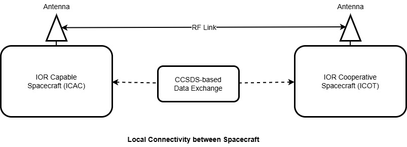
Local Connectivity between Spacecraft
IOR Capable (ICAC) and IOR Cooperative (ICOT) spacecraft support a local inter-spacecraft communication interface for coordination during RPOD operations. This interface is realized over an RF communication link and utilizes CCSDS-based protocols for data exchange.
This document defines the interface requirements at a system level. Detailed implementation aspects, including protocol layering, message encoding, and physical/link specifications, are defined in the Interface Control Document (ICD).
Authority and Control
This section defines the hierarchy of control and decision-making authority across entities participating in IOR operations.
Authority Hierarchy
Authority is defined in a hierarchical model from lowest to highest:
- Client Spacecraft (ICOT)
- Service Vehicle (ICAC / SV)
- IOR Service Provider Ground Segment
- Client Operator Ground Segment
Higher authority entities can override decisions or commands issued by lower authority entities.
Abort Authority
Abort is the highest priority command within the system.
- An Abort command issued by any authorized entity overrides all ongoing activities
- Abort commands take precedence over all operational states and commands
Operational Context
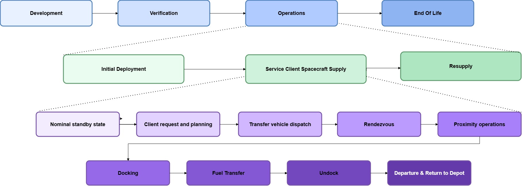
Lifecycle CONOPS
The CONOPS shows where the RPOD sit in the complete product lifecycle. Service Client Spacecraft is part of the Operations Lifecyle.
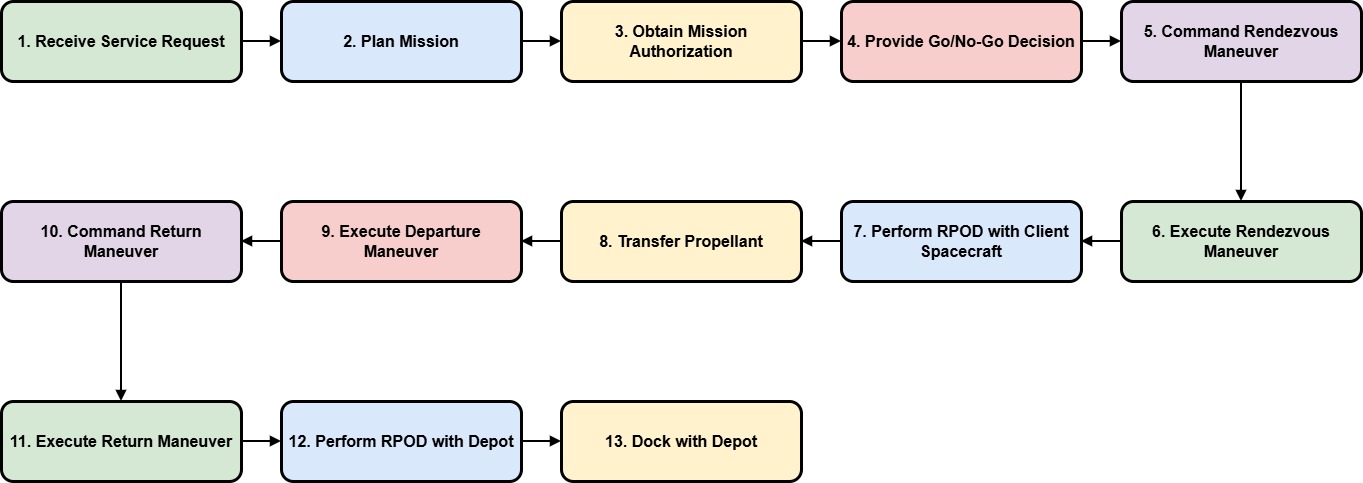
End-To-End Nominal Service Supply
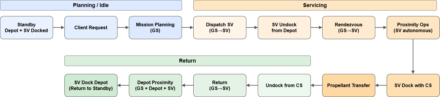
Service Supply
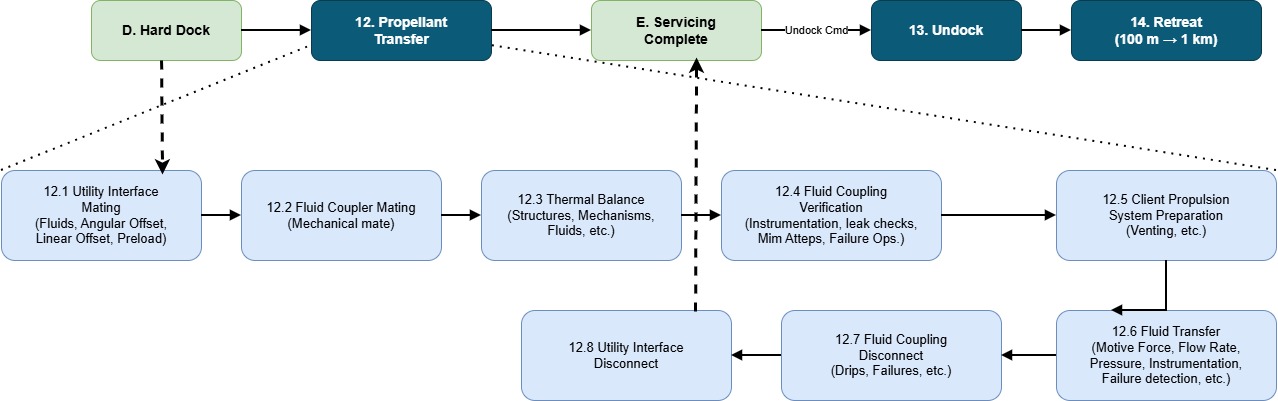
Propellant Transfer
Propellant transfer CONOPS is shown only for completeness. This is a physical interfarce
This CONOPS is used from CONFERS CONOPS as it is. See References. Transfer status are sent from the chaser to the target (see Interaction Flow below)
Interaction Flow
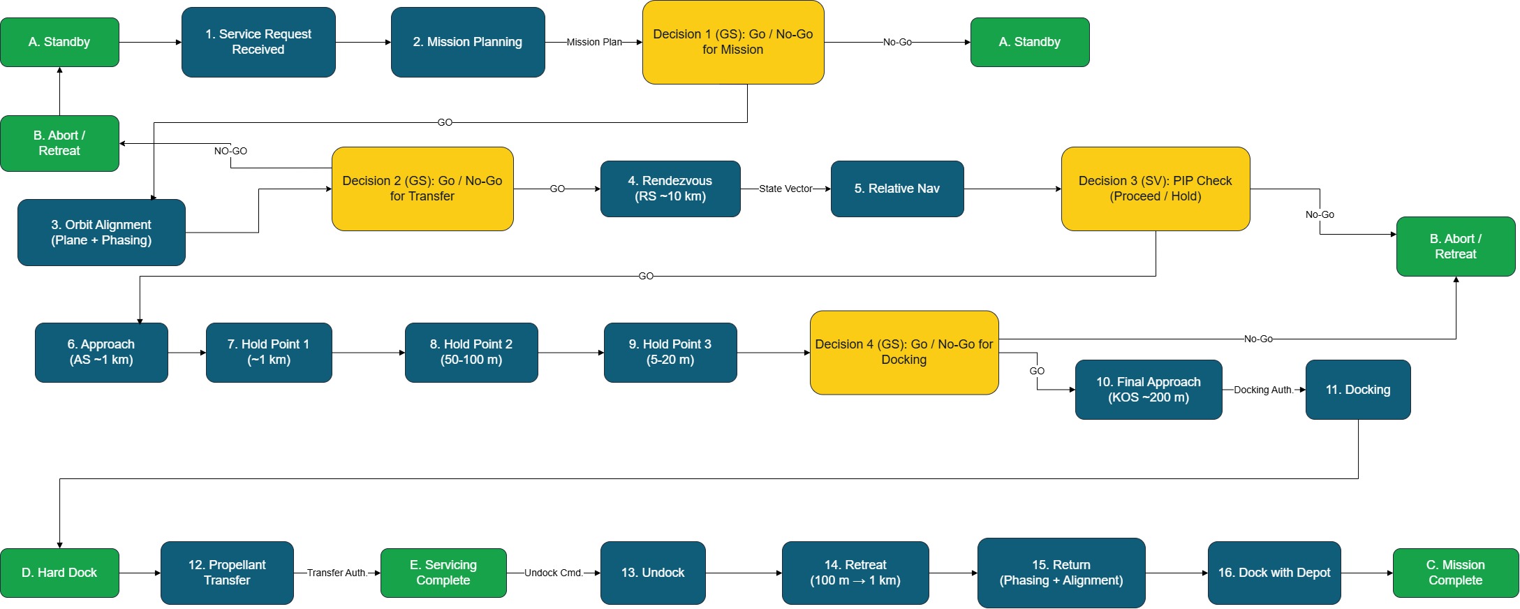
| Step | Phase / State | Chaser Action / Message | Target Response | Notes / Conditions |
|---|---|---|---|---|
| 1 | Pre-RPOD / Orbit Alignment | Driven by GS / ICAC | None | Target not involved |
| 2 | Pre-RPOD / Go-NoGo | Driven by GS | None | Decision gate |
| 3 | Rendezvous / Discovery | Discovery sent every 1 min until ack | DiscoveryAck | Retry until success |
| 4 | Rendezvous / Handshake | InitiateHandshake (5 retries every 2 sec) | HandshakeAck | On failure → Discovery |
| 5 | Relative Nav / Entry Point | RPODState (RENDEZVOUS_ENTRY_POINT_REACHED) | TargetStatus | State sync |
| 6 | Relative Nav / Far Rendezvous | RPODState (FAR_RENDEZVOUS) | TargetStatus | 5 misses → fallback |
| 7 | Decision / PIP Check | ProximityOperationInit (on success) | ProximityOperationReady | Transition |
| 8 | Abort / PIP Failure | Abort (PROXIMITY_OPS, PIP_FAILED, Resume) | None | Controlled abort |
| 9 | Proximity Ops / Approach | RPODState (APPROACH) | None | Chaser-driven |
| 10 | Proximity Ops / Hold Points | RPODState (ENTER_HOLD at HP1–HP3) | None | Multiple holds |
| 11 | Decision / Docking Go-NoGo | ReadyToDock | ReadyToDockConfirmed | Final gate |
| 12 | Alignment / Attitude | PerformAttitudeManeuver | AttitudeManeuverPerformed | Includes acceptance |
| 13 | Docking / Final Decision | ReadyToDock | ReadyToDockConfirmed | Reconfirm |
| 14 | Docking / Initiation | DockingInitiating | None | Start docking |
| 15 | Docking / Complete | DockingComplete | DockingCompleteConfirmed | Dock achieved |
| 16 | Transfer / Ready | ReadyForFuelTransfer | ReadyForFuelTransferConfirmed | Pre-check |
| 17 | Transfer / Start | FuelTransferInitiated | None | Transfer begins |
| 18 | Transfer / Complete | FuelTransferComplete | ReadyForFuelTransferConfirmed | Ready for undock |
| 19 | Undocking / Separation | UndockingInitiating / Completed | None | Separation |
| 20 | Retreat / Retreat | RetreatInitiating + RPODState (RETREAT) | None | Controlled retreat |
| 21 | Return / Exit | RPODState (RETURN) | None | Exit trajectory |
| 22 | Completion / End | ProximityOperationComplete | None | End |
Proximity Operations (Chaser-Driven) State
Proximity operations are managed and executed by the chaser (ICAC).
These states represent internal control and progression of RPOD during close-range operations.
The chaser communicates its current proximity state using RPODState messages.
The target (ICOT) does not actively control these states and is not required to respond, except for safety or higher-level command interactions defined elsewhere.
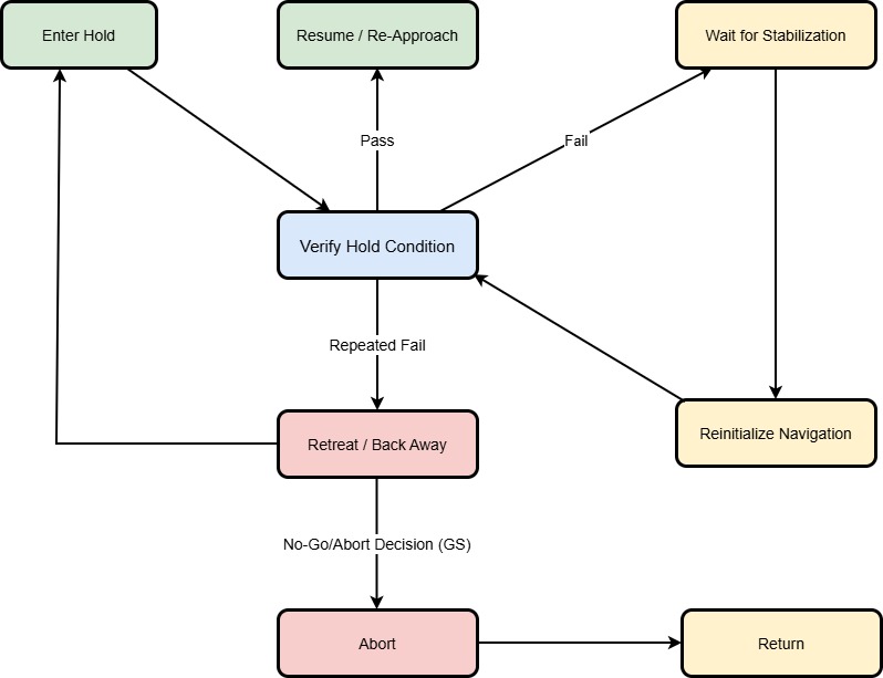
| Step | State | Chaser Action / Message | Notes / Conditions |
|---|---|---|---|
| 1 | Enter Hold | RPODState (Status: PROXIMITY_OPERATIONS, State: ENTER_HOLD) | Command to enter hold point |
| 2 | Verify Hold | RPODState (State: VERIFY_HOLD) | Chaser evaluates stability at hold point |
| 3 | Verify Fail | RPODState (State: RETREAT) | Triggered if stability criteria not met |
| 4 | Verify Pass | RPODState (State: WAIT_FOR_STABILIZATION) | Transition to stabilization monitoring |
| 5 | Stabilized | RPODState (State: VERIFY_HOLD) | Confirms stable condition before proceeding |
| 6 | Stabilization Timeout | RPODState (State: RETREAT) | Triggered if stabilization not achieved within allowed time |
Exchange Message Structures
Used in several communication – between spacecrafts, spacecraft to ground systems.
Spacecraft Classification
Spacecraft Classification originates at any IOR Capable and IOR Cooperative spacecrafts. This message is exchanged as below:
- IOR Capable Spacecraft <→ IOR Cooperative Spacecraft
- IOR Capable Spacecraft <-> IOR Capable Spacecraft
Spacecraft classification provides spacecraft classification fields to represent the sending spacecraft. Not all fields are useful in all spacecraft to spacecraft interactions.
SpacecraftClassifiction {
  Mode: {SERVICE_VEHICLE, DEPOT, CLIENT_SPACECRAFT}
  CapbilityLevel {IOR_ENABLED, IOR_AWARE, IOR_COO[ERATIVE, IOR_CAPABLE} // Valid when Mode =CLIENT_SPACECRAFT
  ComplianceVersion: String
  InterfaceType interfaceType
  PropellantType propellantType
}
Spacecraft State
Spacecraft State message originates at any IOR Capable and IOR Cooperative spacecrafts. This message is exchanged as below:
- IOR Capable Spacecraft <→ IOR Cooperative Spacecraft
- IOR Capable Spacecraft <→ IOR Capable Spacecraft
Spacecraft State provides following state fields representing the state of the sending spacecraft.
SpacecraftState {
  ThermalInfo thermalInfo;
  PropellantInfo propellantInfo;
}

ThermalInfo {
  ThermalNominal boolean;
  Bus_K   double;
  Propulsion_K double;
}

PropellantInfo {
     PropellantType { HYRAZINE | BIPROPELLANTS | XENON | CRYOGENIC }
     PropellantQuanity_Gms double; // mass in grams
     Pressure_bar double; // in bar
     Temprature_K temp; // in Kelvin
}
RPOD State
RPOD state originates at any IOR Capable spacecraft. This message is exchanged as below:
- IOR Capable spacecraft → Ground Segment
- IOR Capable Spacecraft → IOR Cooperative Spacecraft
- IOR Capable Spacecraft ↔︎ IOR Capable Spacecraft
RPODState {
  RPODControlMode: {GS_CONTROLLED | FULL_AUTONOMOUS | AUTONOMOUS_WITH_GS_AUTH}
          //ControlMode does not generally change, but can change in case chaser looser ground connection

  RPODStatus: {ORBIT_TRANSFER | RENDEZVOUS_ENTRY_POINT_REACHED | FAR_RENDEZVOUS | CLOSE_RENDEZVOUS | PROXIMITY_OPERATIONS | RETURN}  NOMINAL_MODE = SV back with Depot

  // ProximityOperationStatus is used with RPODStatus ==  PROXIMITY_OPERATIONS
  ProximityOperationStatus (POS): {APPROACH | ENTER_HOLD | VERIFY_HOLD | WAIT_FOR_STABILIZATION | RETREAT | PROXIMITY_OPER_ABORT | NOMINAL}

  //ProximityState is used with ProximityOperationStatus == NOMINAL
  ProximityState (PRS): { APPROACH | ALIGNEMENT | DOCK | FUEL_TRANSFER | UNDOCK | RETURN | MISSION_ABORT }
}
Spacecraft Relative Nav Info
Spacecraft Relative Navigation Info originates at any IOR Capable spacecraft during RPOD operations. This message is exchanged as below:
- IOR Capable Spacecraft → IOR Cooperative Spacecraft
- IOR Capable Spacecraft <→ IOR Capable Spacecraft
SpacecraftRelativeNavInfo {
  Ephemeris:  {x, y, z, Vx, Vy, Vz}
  Attitude { pitchAngle, yawAngle, rollAngle }
  InView: Yes | No  // Relaative
  RelativeCooridates { x, y, z }  // meters in ECI framework
  RelativeVelocity {Vx, Vy, Vz} // m/s ECI framework
}
Spacecraft Return Plan
Spacecraft Return Plan is sent by IOR Service Provider GS to SV to enable SV to return to REP to enable RPOD operations with the Depot
This message is exchanged as below:
- IOR Service Provider Ground Station → SV
SpacecraftReturnPlans {
  ReturnTrajectory returnTrajectory; // gets the SV to REP
  ContactPlan contactPlan // Contact Plan for SV to use to communicate with IOR Service Provider GS
  DepotEphemeris Ephemeris;
}
Referenced by AbortRefuelService (GS→SV) and by RefuelServicePlans to ensure consistent abort behavior
IOR Refuel Service Plan
IOR Service Provider GS sends the Refuel Service Plan to provide all the necessary details to the SV/Depot to carry out a refuel service request. The IOR Service GS continues to support the SV through the delivery process.
This message is exchanged as below:
- IOR Service Provider Ground Station → SV
IORRefuelServicePlan {
  RPODToClientSpacecraftPlan rpodPlan;
  ContactPlan contactPlan;
  RefuelServiceRequest refuelServiceRequest;
}
Abort Command
Abort Command can can be initiated by any authorized entity:
- IOR Capable Spacecraft
- IOR Cooperative Spacecraft
- IOR Service Supplier Ground Segment
- Client Operator Ground Segment
AbortType {
    ABORT_TYPE_PROXIMITY_OPS,
    ABORT_TYPE_DOCKING,
    ABORT_TYPE_TRANSFER,
    ABORT_TYPE_MISSION
  }

AbortSource {
  CHASER,
  TARGET,
  SERVICE_PROVIDER_GS,
  CLIENT_OPERATOR_GS
  }

AbortReason {
    ABORT_REASON_PIP_FAILED,
    ABORT_REASON_NAV_FAILURE,
    ABORT_REASON_SAFETY_VIOLATION,
    ABORT_REASON_COMMS_LOSS,
    ABORT_REASON_SYSTEM_FAULT
  }

AbortCommand {
  AbortID int;
  AbortSource {CHASER, TARGET, SERVICE_PROVIDER_GS, CLIENT_OPERATOR_GS}
  AbortType abortType;
  AbortReason abortReason;
  AbortTime time;
  NextStage  {RESUME, RETURN, WAIT_FOR_NEXT_STAGE};
}
Data Structures
These data structures are used by
RPOD to Client Spacecraft Plan
RPODToClientSpacecraftPlan {
  TransferAndOrbitPhasing orbitPhasing; // Tracjectory for Orbit Phasiing
  RendezvousEntryPoint {x, y, z} // in kms ECI
  RendezvousSphere {Cx, Cy,Cz, Radius} // in Kms ECI
  HoldPoints holdPoint[N]; // {x, y, z} // in kms ECI
  ApproachSphere {Cx, Cy,Cz, Radius} // in Kms ECI
  KeepOutSphere {Cx, Cy, Cz, Radius} // in Kms ECI
  ACSphere {Cx, Cy, Cz, Radius} // Approach Corridor Sphere, Radius in m, ECI
  ApproachCorridor {Rbar, VBar, Length,  ACSphere}
}
Contact Window
Contact Window is the time window when two entities can contact each other
ContactWindow {
   ContactType {RF_LSL, RF_HSL} // Low speed, High speed links
   StartTime time;
   EndTime time;
   Entity entityDst;
   RequiresPointing boolean;
   PointingDirection {x, y, z};
}
Contact Plan
Contact Plan Windows SV/Depot to communicate through during service delivery
ContactPlan {
      Entity entitySrc;  // Who is the contact plan for
      ContactWindow contactWindow[ContactPeriod]
}
Refuel Service Request
Refuel Service Request is what was received from the client either manually or from the Client Operator Ground Segment.
RefuelServiceRequest {
  Client Spacecraft ID
  ClientType
  Propellant type
  Requested volume
  Client spacecraft ephemeris data
  Abort/Return Plan Reference
  SV Abort/Return Plan
}
Compliance Framework
The IOR compliance framework consists of Interface Requirements Documents (IRD), Interface Control Documents (ICD), test suites, and compliance validation services.
Path to Compliance (ICD, Verification and Validation)
- Develop IOR system components aligned with the defined IRD and corresponding ICD specifications
- Execute system validation using the IOR Initiative QA and test platform
- Run defined test suites to verify interface compliance, interoperability, and operational behavior
- Undergo compliance assessment and certification
Appendix: Acronyms, Definitions, RPOD terms
RPOD Related Terms (Adapted from IRSIS & CONFERS)
Terms adapted from International Rendezvous System Interoperability Standards (IRSIS) for IOR
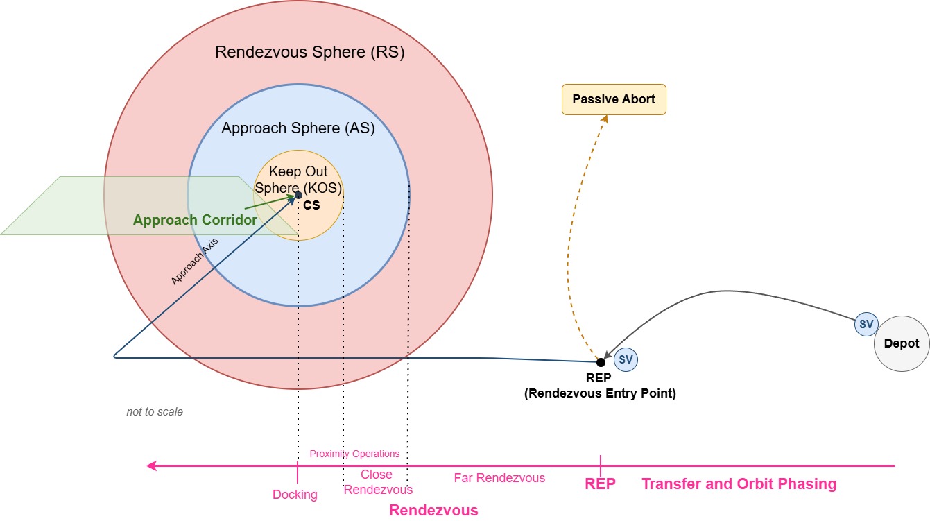
- Operation Regions and Zones
- Rendezvous Sphere (RS) – Radius: 10 Kms around client space craft. Safe to abort in this region
- Approach Sphere (AS) – The AS is a 1 km radius sphere centered at the target vehicle center of mass.
- Keep-out Sphere (KOS) – The KOS is 200 meter radius sphere centered at the target vehicle center of mass.
- Approach/Departure Corridors – The Approach and Departure corridors are ±10° centered to the docking port axis within the KOS
- Abort (Passive Abort) – Safe trajectory ensuring collision avoidance without active control
- Approach Axis – The predefined relative line of approach from the chaser to the target used during final approach (e.g., along R-bar, V-bar, or docking port axis).
- Corridor – A bounded 3D operational region around the target within which specific RPOD maneuvers are permitted under defined constraints (relative position, velocity, and safety rules). The following corridors are defined by IRSIS
- Approach Corridor – Region within which the chaser is authorized to perform controlled approach toward the target.
- Departure Corridor – Region defining the safe path for retreat or departure away from the target.
- Relocation Corridor – Region used for lateral or orbital repositioning maneuvers around the target without initiating final approach or departure.
- Abort Corridor Predefined safe escape path the chaser follows upon abort to rapidly increase separation.
- Automatic Abort Corridor
- Manual Abort Corridor
- Mating Envelopes – The allowable relative position, orientation, and velocity limits within which mating (capture or docking) can safely occur.
- Capture Envelope – Broader tolerance limits within which initial contact or soft capture mechanisms can successfully engage prior to docking.
- Docking Envelop – Tight tolerance limits for relative position, attitude alignment, and closing velocity required for hard docking interface engagement.
- Visiting Vehicle – Also called Chaser in IOR is Service Vehicle.
- Transfer and Orbit Phasing – Transfer and Orbit Phase includes departure from Depot and reach to the start of Rendezvous. This phase in managed by IOR Operator team operates the mission along with real-time state vector of client space craft is received from the client operator. Transfer and Orbit Phasing aligns plane (i.e. RAAN), altitude and timing (phase angles), so the chaser arrives at Rendezvous Insertion (RI) with correct geometry.
- Target Phasing (TP) – Same as Transfer and Orbit Phasing
- Rendezvous Entry Point (REP) – Point in space when the Transfer and Orbit Phasing completes
- Rendezvous – This phase begins at REP when chaser/SV is in a co-orbital relative state with the client and transitions to relative navigation; ends at docking start.
- Far Rendezvous (FR) – FR navigation is managed by IOR operator via Ground Segment until the Approach Sphere is successfully achieved. This phase enables passively abort the approach on a trajectory that is operationally safe. This phase ends when reaching the Approach Sphere.
- Close Rendezvous Phase within the Approach Sphere (AS) where the service vehicle performs controlled relative motion operations including Approach and Fly-around, leading to final alignment and KOS entry
- Approach – This phase starts with a Go/No Go decision. A go decision triggers the Approach Initiation (AI) burn. The service vehicle transitions to the approach axis while in the Approach Sphere.
- Fly-around – Consists of a service vehicle maneuver during approach or departure in which the service vehicle transitions to another approach axis, or circumnavigates the target vehicle and returns to an approach axis.
- Keep-Out Sphere (KOS) – Protected zone; entry only via corridor
- Proximity Operations – All operations within Approach Sphere, including Approach and Fly-around, docking, undocking and departure/retreat. This phase includes Close Rendezvous phases above: Approach, Fly-around. These operations are performed in the Approach Sphere (AS) (used extensively within the NASA ISS community)
- Docking – Defined as the docking mechanism contact, capture and hard-mate. Docking begins at the time of initial contact of the vehicles’ docking mechanisms and concludes when hard-mating hooks/latches have been fully engaged. After first contact, rendezvous phase is complete. This phase is owned by the docking mechanism.
- Undocking – Defined as the physical separation of the two vehicles.
- Departure – For release and departure, the phase commences upon physical separation, either docking mechanism push-off or grapple release, from the target spacecraft (host platform). This phase is complete when the service vehicle is confirmed to be departing on a trajectory that is operationally safe and the visiting vehicle is outside the AS.
- Retreat – Defined as the service vehicle increasing its relative range with respect to the target client spacecraft, aiming at a predefined hold point.
- Hold – In this phase, the service vehicle maintains its relative position with respect to the target spacecraft such that it neither approaches nor retreats from the target.
- Free Drift – In this phase, the target client space craft’s and the visiting vehicle’s translational and rotational controls are inhibited. This phase is initiated at first contact for docking
- Abort – This phase is initiated automatically or by crew (chaser or target) for the service vehicle to perform a separation sequence (thruster firing), which places the service vehicle on a safe trajectory departing from the target.
Industry Terms and Definitions
- Fuel Shuttle – Shuttle that services the spacecraft. Also called Service Vehicle (SV)
- Fuel Station – A space craft which stores the fuel or propellant, also called Fuel Depot or Depot
- Fuel Depot – Same as Fuel Station also called Depot.
- Service Orbit (SO)– Orbit in which Depot & SV reside in nominal state. SO is selected for optimal delivery to SV.
- Service Vehicle – Same as Fuel Shuttle
- R-Bar Maneuvers for the service spacecraft (chaser) to meet the target by travelling along the radial vector (R-Bar), which points toward or away from the Earth’s centre.
- V-Bar Maneuvers for the service spacecraft (chaser) to meet the target by approaching along the velocity vector (V-Bar) of the target, i.e., moving from ahead of or behind the target along its direction of motion.
- Z-Bar Maneuvers Maneuvers for the service spacecraft (chaser) to meet the target by approaching orthogonally to the orbital plane (Z-Bar), i.e., along the cross-track direction normal to both the R-Bar and V-Bar.
Acronyms
- ADCS – Attitude Determination & Control System. It is control logic. Handles pointing / rotation (pitch, roll, yaw)
- AS – Approach Sphere around the target (~10 km → ~1 km in radius)
- AR&C – Autonomous Rendezvous and Capture
- CCSDS SPP – CCSDS Space Packet Protocol https://ccsds.org/Pubs/133x0b2e2.pdf
- DSO – Dynamic Space Operations
- ECEF – Earth-Centered Earth-Fixed. Used for ground locations.
- ECI – Earth Central Inertial – uses for orbits, spacecraft trajectory
- GGNS – Guidance, Navigation and Control System
- GN&C – Guidance Navigation and Control.
- ISRFL – Inter Satellite RF Link. RF link between two spacecraft. This is used for example for IOR Cooperative RPOD operations.
- T&M – Telemetry and Monitoring
- ISAM – In-space Servicing, Manufacturing, and Assembly
- KOS – Keep-Out Sphere (~100–200 m between target and chaser). Also called Keep-out Zone.
- LVLH – Local Vertical Local Horizontal
- OPS – Operational
- PRM – Northrop Grumman’s Passive Refueling Module
- RAFTI – Orbit Fab’s Rapidly Attachable Fluid Transfer Interface
- REP – Rendezvous Entry Point (~10s km → ~10 km). Rendezvous operations begin at the Rendezvous Entry Point (REP).
- RS – Rendezvous Sphere
- RPOD – Rendezvous, Proximity Operations, Docking
- SERB – Space System Command’s System Engineering Review Board
- SSM – sustained space maneuver
- STM – Space Traffic Management
- TACS – Target Vehicle Analysis Coordinate System. Coordinate system aligned with Target/client space craft. See IRSIS document.
- TLM – Telemetry
- TT&C – Telemetry, Tracking and Command