|
Document/Purpose |
|
| Traceability (Upstream /Downstream) Documents | Upstream: 1.3 Concept of Operations (CONOPS) Downstream: 1.4 System Requirements, 1.6 Logical Architecture |
| Status | pre-DRAFT |
| Baseline Version/Date | Current Version | Not yet established | v0.1 |
| Last Updated | |
| Owner / Lead | Sanjay Chadha |
| Contributors | |
| Reviewers | |
| Scope/Out-Of-Scope | Scope: System Design, System Requirements, System Analysis, Out-of-Scope: Physical Architecture |
| Notes | Functional Flow Block Diagrams (FFBD) – Classic DoD/Aerospace
Functional Decomposition SysML – Activity Diagrams SysML v2 – Action usage decomposition, Function Definition and function usages |
Table of Contents
- IOR Spacecraft Capability Levels
- IOR Enabled Capability Requirements
- IOR Aware Capability Requirements
- IOR Cooperative Capability Requirements
- IOR Capable Capability Requirements
- Client Operator Ground System
- IOR Operator
- Conjunction Service Provider
- Space Environment / Debris
- IOR Ground System <-> Depot
- IOR Ground System <-> Service Vehicle
- Depot <-> Service Vehicle
- Nominal Service to Client Space Craft
- Execute Rendezvous
- Execute RPOD with Client Spacecraft
- Propellant Transfer
- Abort Far Rendezvous
- RPOD Recovery (Generic)
- 1. Ground Segment
- 1.2 Mission Planning and Execution
- 1.4 Space Communications Management
- 1.6 RPOD Mission Management
- 1.8 Resupply Mission Management
- 2. IOR Space Segment
- 2.1 Depot
- 2.1.1 Communications Management (GS Interface)
- 2.1.2 RPOD Interface with Vehicles
- 2.1.3 Attitude Control
- 2.1.4 Service Vehicle Interface
- 2.1.5 Maneuver Execution
- 2.1.6 Navigation Data Management
- 2.1.7 Telemetry Generation
- 2.1.8 Propellant Storage Management
- 2.1.9 Fault Management
- 2.1.10 Health Monitoring
- 2.2 Service Vehicle (SV)
- 2.2.1 Communications Management (GS Interface)
- 2.2.2 Navigation Data Management
- 2.2.3 RPOD Operations
- 2.2.4 Safety Management
- 2.2.5 Relative Navigation
- 2.2.6 Propellant Transfer Operations
- 2.2.7 Maneuver Execution
- 2.2.8 Propellant Inventory Management
- 2.2.9 Health Monitoring and Diagnostics
- 2.2.10 Depot Interface
Functional Overview
This section defines the major functional activities required to support the In-Orbit Refueling (IOR) mission. Functions are organized by operational segment (Ground Segment and Space Segment) to clarify operational responsibilities. Detailed subsystem allocation will be refined in later architecture stages.
IOR Spacecraft Capability Levels
Four levels of spacecraft capability are defined, with more details here. These capabilities define the minimum requirements for an entity to be classified as IOR Enabled, IOR Aware, IOR Cooperative and IOR Capable within this initiative.
The Depot, Service Vehicle (SV), Resupply Vehicle (RV), and IOR Capable Client Spacecraft (CS) share IOR Capable as a common set of capability level – enabling cooperative proximity operations and refueling.
IOR Enabled Capability Requirements
Physical Interface
These are Physical Interfaces between SV, Depot, Client Craft and Resupply Vehicle.
Space System Command’s System Engineering Review Board (SERB) has two approved standard interfaces for satellite refueling –
- Northrop Grumman’s Passive Refueling Module (PRM) and
- Orbit Fab’s Rapidly Attachable Fluid Transfer Interface (RAFTI).
Industry solutions for refueling of National Security Space assets equipped with these SERB-approved interfaces are sought to meet sustained space maneuver (SSM) needs by 2030
IOR Aware Capability Requirements
Autonomy
- Must be able to operate in autonomous mode with guidance from Ground Station
- Must accept only abort/override commands from Ground Station during autonomous operations
Ground Communication
- Must be able to send proximity operation status to Ground Station via defined communication path
- Operation status must include: DOCKED | UNDOCKED | PROPELLANT_AMOUNT (units). Increasing propellant amount indicates propellant transfer is in progress or is complete.
IOR Cooperative Capability Requirements
Each IOR Cooperative spacecraft must assist active and autonomous participation in proximity operations and refueling through communication and support capabilities.
Autonomy
- Must be able to operate in fully autonomous mode
- Must accept only abort/override commands from Ground Station during autonomous operations
Communication (Local and Ground)
- Must support RF-based local communication with partner spacecraft
- Must communicate using CCSDS Space Packet Protocol
- Must transmit proximity operation status to Ground Station via defined communication path
Attitude & Ephemeris Awareness and Control
- Must determine its own orientation (attitude determination)
- Must maneuver to commanded orientation
- Must autonomously control yaw, pitch, and roll to achieve required attitude
- Must generate and maintain ephemeris data (position and velocity state)
IOR Capable Capability Requirements
Each IOR Capable spacecraft must be able to completely execute RPOD and transfer operations as a master (chaser) and assist the master in RPOD and transfer operations as a slave (target).
IOR capable in addition to IOR Cooperative must have these capabilities
Sensing
- Must provide LiDAR-based relative sensing capability
Control Structure and Coordination Processing
- Must support establishment of a master–slave configuration (default or negotiated)
- Must support operation in either master or slave role
- Must process master–slave attitude coordination logic
- Must generate and transmit attitude-related commands to partner spacecraft when acting as master
IOR Capable RPOD Role Allocation
Although these entities implement the same capabilities, they perform different roles depending on the RPOD scenario.
| Proximity Pair | Master | Docking Vehicle | Propellant Supplier |
|---|---|---|---|
| Depot – RV | RV | RV | RV |
| Depot – SV | SV | RV | Depot* |
| SV – CS | SV | SV | SV |
*Depot transfers propellant to SV before the next supply mission. The transfer of propellant is not tied to this RPOD and can happen at any later time.
External Actors and Interfaces
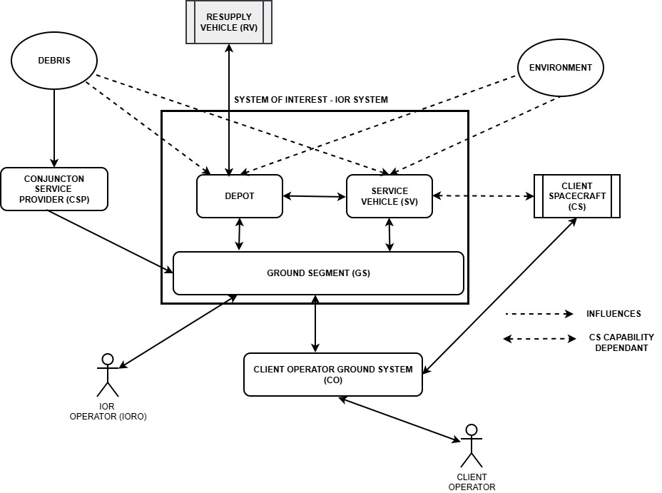
Client Operator Ground System
- The client’s ground system interfaces with IOR systems ground system and coordinates the supply mission with IOR Ground Systems.
- Interfaces with: GS
Exchanges
- Sends Go / No-Go authorization inputs
- Sends client spacecraft status, ephemeris, and health information
- Sends RPOD status information (for IOR-aware / cooperative spacecraft)
- Receives service vehicle status, ephemeris, and health information to support decision-making
- Receives Go / No-Go decisions for mission execution
IOR Operator
- Supervises mission execution and provides operational control authority
- Interfaces with: Ground Segment (GS)
Exchanges
- Initiates mission execution
- Issues abort commands
- Provides Go / No-Go decisions
- Reviews mission status and performance data
- Initiates anomaly response actions
Conjunction Service Provider
- Provides collision risk data
- Interfaces with: Ground Segment (GS)
- Exchanges:
- Sends conjunction alerts
- Sends collision risk data
Space Environment / Debris
- External influence on system behavior
- Interfaces with: Depot, Service Vehicle
- Exchanges:
- Environmental disturbances
- Collision risk exposure
Internal Interfaces
IOR Ground System <-> Depot
IOR Ground System to Depot
- Sends operational commands
a. Authorization
b. Go/No Decision
c. Maneuver Commands - Sends Mission States data
Depot to IOR Ground System
- Sends telemetry and status information
a. Ephemeris data
b. Health and resource status of Depot
c. Health and resource status of Service Vehicle
d. Proximity Operation Status
e. Propellant information - Sends Go/No status/assessment for depot-controlled operations
IOR Ground System <-> Service Vehicle
IOR Ground System to Service Vehicle
- Provides telemetry and status information
- Ephemeris data
- Health and resource status of Depot
- Health and resource status of Service Vehicle
- Propellant information
- Provides RPOD status
- Proximity operations status
- Hold point status
- Docking status
- Propellant transfer status
- Undocking and departure status
- Sends Go/No status or assessment for service vehicle-controlled operations
Depot <-> Service Vehicle
Depot to Service Vehicle
- Provides Operational commands while SV docked
- Start
- Operational Health status
- propellant status
- docking status
- Provides RPOD guidance commands during proximity operations
- Relative Navigational Guidance
Service Vehicle to Depot
- Status responses when docked to Depot SV
- Operational Health status
- Propellant status
- Docking complete
- RPOD responses while SV in RPOD operations with Depot
- Local Navigational Status
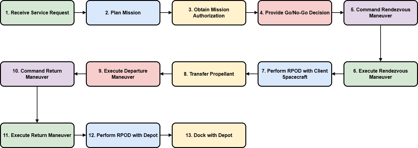
Functional Chain
Nominal Service to Client Space Craft
| SNO | Function | Responsible |
|
|
Receive service request | GS |
|
|
Plan Mission | GS |
|
|
Obtain Mission Authorization | GS |
|
|
Provide Go/No Go decision | GS |
|
|
Command rendezvous maneuver | GS |
|
|
Execute rendezvous maneuver | SV |
|
|
Perform RPOD with client spacecraft | SV |
|
|
Transfer Propellant | SV |
|
|
Execute departure maneuver | SV |
| 10. | Command Return maneuver | GS |
| 11. | Execute return maneuver | SV |
| 12. | Perform RPOD with depot | SV + Depot |
| 13. | Dock with Depot | SV |
Upstream
Downstream
- To be defined in System Requirements
Execute Rendezvous
| SNO | Function | Responsible |
| 5.1 | Plan orbit alignment | GS |
| 5.2 | Command phase alignment maneuver | GS |
| 5.3 | Execute phase alignment maneuver | SV |
| 5.4 | Perform PIP check | SV |
| 5.5 | Provide Go/No Go status | SV |
Upstream
Downstream
- To be defined in System Requirements
Execute RPOD with Client Spacecraft
| SNO | Function | Responsible |
| 6.1 | Perform approach to hold point 1 | SV |
| 6.2 | Verify hold point 1 | SV |
| 6.3 | Perform approach to hold point 2 | SV |
| 6.4 | Verify hold point 2 | SV |
| 6.5 | Perform Alignment for Docking | SV |
| 6.6 | Perform Soft Docking | SV |
| 6.7 | Perform Hard Docking | SV |
Upstream
Downstream
- To be defined in System Requirements
Propellant Transfer
Refer to Client Space craft capability levels
Satellite Capability Level: IOR Enabled
| SNO | Function | Responsible |
| 8.1 | Mate Utility Interface | SV |
| 8.2 | Mate Fluid Coupler | SV |
| 8.3 | Verify Thermal Balance | SV |
| 84 | Verify Fluid Coupling | SV |
| 8.5 | Prepare Client Propulsion system | SV+CS |
| 8.6 | Transfer Fluid | SV + CS |
| 8.7 | Disconnect Fluid Coupling | SV |
| 8.8 | Disconnect Utility Interface | SV |
Satellite Capability Level: IOR Cooperative
| SNO | Function | Responsible |
| 8.1 | Mate Utility Interface | SV + CS |
| 8.2 | Mate Fluid Coupler | SV + CS |
| 8.3 | Verify Thermal Balance | SV + CS |
| 84 | Verify Fluid Coupling | SV + CS |
| 8.5 | Prepare Client Propulsion system | CS |
| 8.6 | Transfer Fluid | SV (primary) + CS (support/feedback) |
| 8.7 | Disconnect Fluid Coupling | SV |
| 8.8 | Disconnect Utility Interface | SV |
Upstream
- To be defined in OPCONS
Downstream
- To be defined in System Requirements
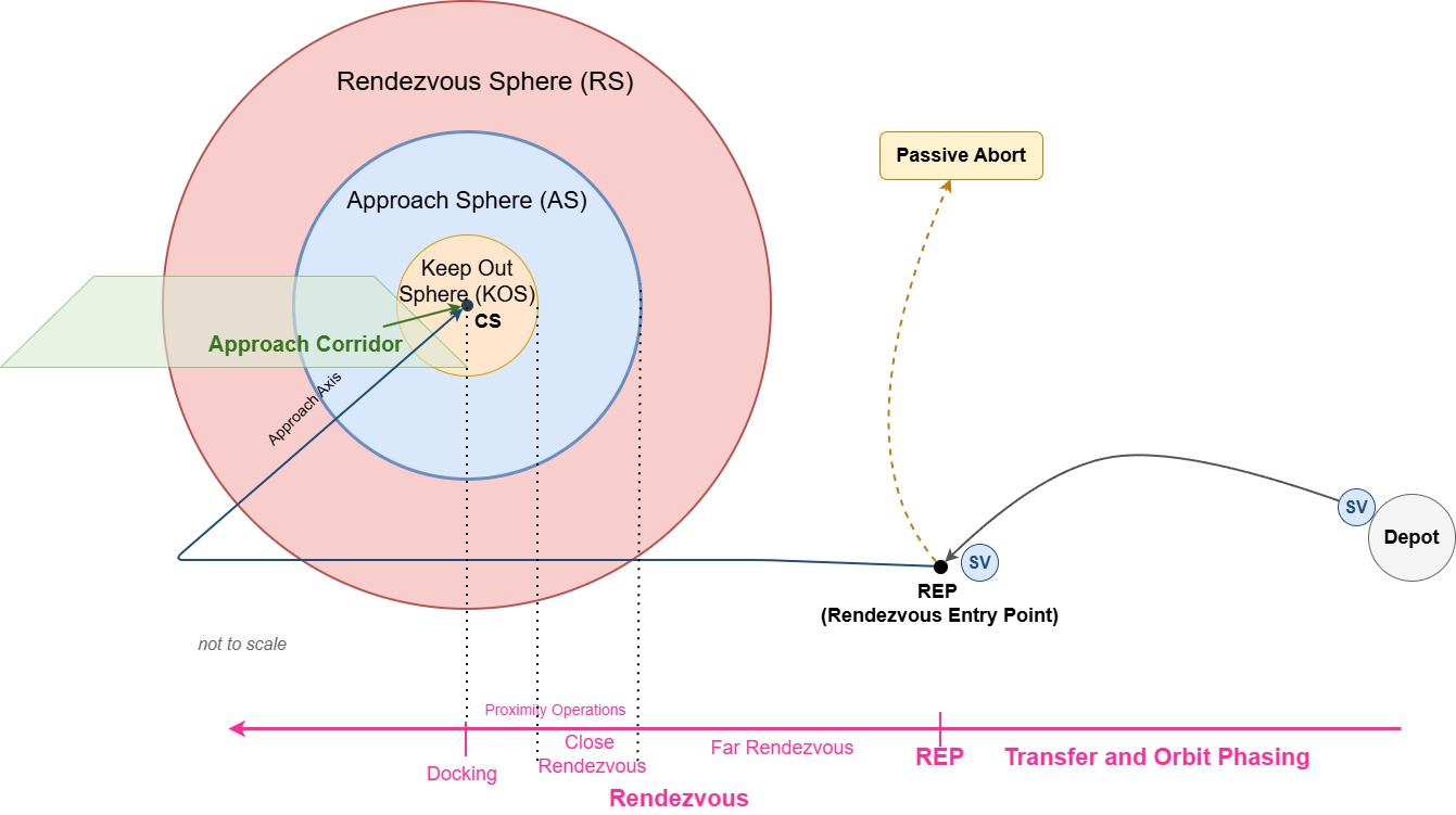
Abort Far Rendezvous
Scenario (clean and realistic)
- SV at ~10 km → performing rendezvous
- CSP sends updated conjunction data
- Collision probability exceeds threshold
- GS declares No-Go / Abort
| SNO | Function | Responsible |
|
|
Process Collision Alert data from CSP | GS |
|
|
Assess Collision Risk / Decide Abort | GS |
|
|
Command Abort / Retreat Maneuver | GS |
|
|
Command retreat maneuver to SV | GS |
|
|
Execute retreat maneuver | SV |
|
|
Monitor Separation / Confirm Safe State | GS |
Upstream
- To be defined in OPCONS
Downstream
- To be defined in System Requirements
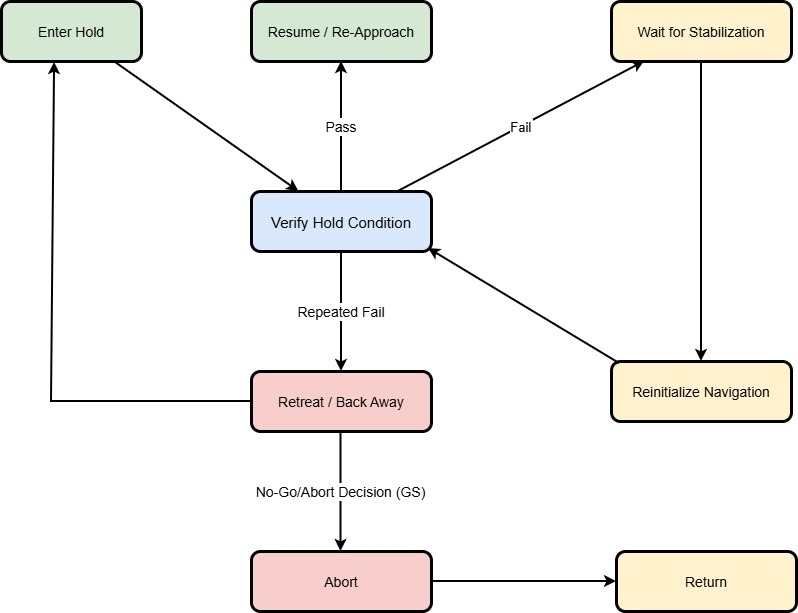
RPOD Recovery (Generic)
Generic recovery logic applicable to approach, hold points, and proximity operations.
For this system, RPOD recovery is driven by navigation and configuration integrity. Two realistic trigger scenarios are:
- Relative navigation inconsistency / sensor anomaly
RPOD relies on precise relative navigation. If navigation data becomes inconsistent or unreliable, the Service Vehicle enters Hold, re-verifies conditions, may reinitialize navigation, and resumes operations only after consistency is restored. - Target attitude or docking geometry out of limits
Docking requires controlled alignment and stable attitude. If limits are exceeded, the Service Vehicle enters Hold or performs a limited Retreat / Back Away, waits for stabilization, and then re-approaches once conditions are acceptable.
Recovery is therefore the primary response, preserving mission progress and propellant.
Abort is the last resort, used only when recovery attempts fail or safe conditions cannot be re-established.
This functional chain models that behavior explicitly
| SNO | Function | Responsible |
|
|
Enter Hold SV | SV |
|
|
Verify Hold Condition | SV + GS |
|
|
Wait for Stabilization (if verify fails) | SV |
|
|
Reinitialize Navigation | SV |
|
|
Verify Hold Condition | SV + GS |
|
|
Command Retreat / Back Away (after repeated failure) | GS |
|
|
Execute Retreat / Back Away | SV |
|
|
Enter Hold (post-retreat) | SV |
|
|
Command Resume / Re-Approach (if verify passes) | GS |
| 10. | Resume / Re-Approach | SV |
| 11 | Assess Recovery Outcome / Decide No-Go / Abort | SV/GS |
| 12 | Decide Abort | GS |
| 13 | Transition to Abort State | SV |
| 14 | Execute Safe Separation Maneuver | SV |
| 15 | Provide Return-to-Depot Maneuver Commands | GS |
| 16 | Execute Return-to-Depot Maneuver | SV |
Upstream
- To be defined in OPCONS
Downstream
- To be defined in System Requirements
Functional Decomposition
1. Ground Segment
1.1 Mission Management
- Provides Go / No-Go decision authority
- Authorizes mission execution
- Coordinates anomaly resolution
1.2 Mission Planning and Execution
- Plans service missions
- Designs trajectories for service vehicle operations
- Plans plane alignment maneuvers
- Plans phasing maneuvers
- Plans return-to-depot missions
- Plans abort and contingency missions
1.3 Client Interface
- Manages interaction with client ground system
- Receives and processes service requests
- Coordinates service negotiation and confirmation
- Exchanges mission status and coordination information with client
1.4 Space Communications Management
- Provides communication capability with space assets (SV, Depot)
- Transmits operational commands to space assets
- Receives telemetry from space assets
1.5 Navigation Data Management
- Maintains knowledge of space asset states
- Processes ephemeris for Depot, Service Vehicle, and Client spacecraft
- Determines orbital and relative states of space assets
- Assesses relative positioning for proximity and separation management
1.6 RPOD Mission Management
- Plans RPOD operations
- Authorizes RPOD execution
- Manages proximity operations
- Monitors RPOD operational status
1.7 Return-to-Depot Management
- Plans return-to-depot trajectory for Service Vehicle
- Commands return maneuvers
- Monitors Service Vehicle trajectory
- Monitors relative positioning between Service Vehicle and Depot
1.8 Resupply Mission Management
- Plans resupply missions
- Commands resupply maneuvers
- Monitors maneuver execution
1.9 Collision Risk Management
- Conjunction monitoring
- Avoidance maneuver planning
1.10 Maneuver Management
- Maneuver command generation
- Maneuver execution monitoring
1.11 Propellant Logistics Monitoring
- Depot inventory monitoring
- Service allocation tracking
1.12 Fault Management
- Safe-mode command
- Recovery coordination
1.13 System Health Monitoring
- Vehicle health assessment
- Mission status reporting
2. IOR Space Segment
2.1 Depot
2.1.1 Communications Management (GS Interface)
- Provides communication capability with Ground Segment
- Receives operational commands from Ground Segment
- Transmits telemetry to Ground Segment
2.1.2 RPOD Interface with Vehicles
- Manages proximity operations with Service Vehicle
- Manages docking interface
- Manages undocking operations
2.1.3 Attitude Control
- Controls attitude during docking operations
2.1.4 Service Vehicle Interface
- Manages mechanical interface with Service Vehicle
- Manages propellant transfer interface
2.1.5 Maneuver Execution
- Executes maneuver commands
2.1.6 Navigation Data Management
- Generates ephemeris
- Determines orbital state
2.1.7 Telemetry Generation
- Generates telemetry data
2.1.8 Propellant Storage Management
- Tracks propellant inventory
- Manages propellant conditioning
2.1.9 Fault Management
- Activates safe mode
- Performs system recovery
2.1.10 Health Monitoring
- Monitors depot subsystem health
- Monitors Service Vehicle health when SV is docked to Depot
2.2 Service Vehicle (SV)
2.2.1 Communications Management (GS Interface)
- Provides communication capability with Ground Segment
- Receives operational commands from Ground Segment
- Transmits telemetry to Ground Segment
2.2.2 Navigation Data Management
- Generates ephemeris
- Determines orbital and relative state
2.2.3 RPOD Operations
- Manages proximity operations
- Manages hold points
- Performs docking operations
- Performs undocking operations
2.2.4 Safety Management
- Verifies Go / No-Go conditions for RPOD operations
- Executes abort maneuvers
2.2.5 Relative Navigation
- Tracks target spacecraft
- Generates guidance solutions for RPOD
2.2.6 Propellant Transfer Operations
- Controls propellant transfer
- Monitors propellant flow
2.2.7 Maneuver Execution
- Executes maneuver commands
2.2.8 Propellant Inventory Management
- Tracks onboard propellant inventory
2.2.9 Health Monitoring and Diagnostics
- Monitors Service Vehicle subsystem health
- Performs fault diagnostics
2.2.10 Depot Interface
- Manages mechanical interface with Depot
- Manages propellant transfer interface
- Transmits Service Vehicle health status when docked to Depot
Functional Allocation
| Function |
Ground Segment |
Service Vehicle (SV) |
Depot |
| Client Interface / Service Request Handling |
✔ |
|
|
| Mission Authorization (Go / No-Go) |
✔ |
|
|
| Mission Planning / Service Planning |
✔ |
|
|
| Trajectory Planning |
✔ |
|
|
| Plane Alignment Maneuver |
Plan |
Execute |
|
| Phasing Maneuver |
Plan |
Execute |
|
| Maneuver Command Generation |
✔ |
|
|
| Maneuver Execution |
|
✔ |
✔ |
| Communications Management |
✔ |
✔ |
✔ |
| Telemetry Generation / Transmission |
|
✔ |
✔ |
| Telemetry Reception / Monitoring |
✔ |
|
|
| Ephemeris Management |
✔ |
✔ |
✔ |
| Relative Navigation |
|
✔ |
|
| RPOD Operations Management |
✔ |
✔ |
✔ |
| Proximity Operations |
|
✔ |
✔ |
| Hold Point Management |
|
✔ |
|
| Docking Operations |
|
✔ |
✔ |
| Undocking Operations |
|
✔ |
✔ |
| Propellant Transfer |
|
✔ |
✔ |
| Propellant Inventory Management |
✔ |
✔ |
✔ |
| Return-to-Depot Operations |
Plan |
Execute |
|
| Collision Monitoring |
✔ |
|
|
| Collision Avoidance Maneuver |
Plan |
Execute |
Execute |
| System Health Monitoring |
✔ |
✔ |
✔ |
| Fault Detection / Safe Mode |
✔ |
✔ |
✔ |
| Abort Management |
✔ |
✔ |
|
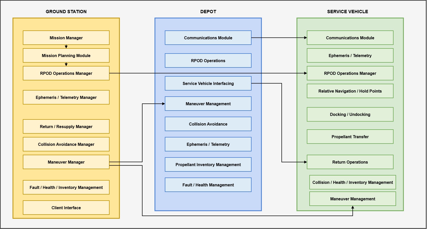
Functional Block Diagram
The activities are listed above, but are not added in the functional block diagram below to make the FBD easy to understand.