| Document/Purpose | |
| Traceability (Upstream /Downstream) Documents | Upstream: 1.5 Functional Architecture and Activities Downstream: 1.7 Physical Architecture |
| Status | pre-DRAFT |
| Baseline Version/Date | Current Version | Not yet established | v0.1 |
| Last Updated | |
| Owner / Lead | Sanjay Chadha |
| Contributors | |
| Reviewers | |
| Scope/Out-Of-Scope | Scope: Out-of-Scope: |
Table of Contents
- ISP GS logical components
- External entities referenced
- Ground Segment Server (GSS) <->Mission Control System (MCS)
- Ground Segment Server (GSS) ↔ Landing Station Manager (LSM)
- Landing Station Manager (LSM) ↔︎ Spacecraft (SC)
- Ground Segment Server (GSS)↔︎ Spacecraft (SC)
- IOR Capable Spacecraft
- ReFuel Orchestrator (RFO)↔︎ Proximity Operations Subsystem (POS)
- ReFuel Orchestrator (RFO)↔︎ GNC
- ReFuel Orchestrator (RFO)↔︎ PRopulsion System (PRS)
- ReFuel Orchestrator (RFO)↔︎Docking and Refueling System (DRS)
- IOR Cooperative Spacecraft
IOR Service Provider (ISP) Ground Segment (GS)
The IOR Service Provider (ISP) Ground Segment (GS) is decomposed here into logical components and their responsibilities. Detailed system boundary and external interfaces are defined in 1.8 Boundaries and Interfaces: 1.8 Boundaries and Interfaces
Allocation of these logical components to physical infrastructure is covered in 1.7 Physical Architecture
ISP GS logical components
| SNO | Logical Component | Acronym | Primary Responsibilities (Logical) |
|---|---|---|---|
| 1 | Ground Segment Server | GSS | Orchestrates end-to-end GS operations; routes and records mission data; triggers planning computations; distributes plans; consolidates telemetry, ephemeris, and status products for downstream systems and operators. |
| 2 | Landing Station Manager | LSM | Distributes contact/hopping plans to Landing Stations and to spacecraft through the Landing Stations; relays applicable plan segments via the landing station network. |
| 3 | Mission Control System | MCS | Computes mission plans, including: (1) Contact Plans (CP) – time-tagged contact windows between spacecraft and landing stations; (2) Service Delivery Plans (SDP) – maneuver/trajectory plans for target and phase alignment; (3) Service Plans (SP) – time-tagged plans describing when and how service is delivered to client spacecraft. |
| 4 | Client Operator Communication Server | CCS | Manages communications and data exchange between the Ground Segment and Client Operators (CO), including operator requests, notifications, and delivery of approved mission products. |
| 5 | IOR Operator Subsystem | IOROS | Human-facing operator interface for IOR operations, monitoring, and manual interventions consistent with the GS operational concept. |
External entities referenced
- Landing Stations (LS): External 3rd-party ground assets distributed globally. Landing Stations provide space/terrestrial connectivity during valid contact windows.
- Spacecraft (SC): Generic term for IOR-cooperative spacecraft (SV, Depot, Resupply Vehicle) and, when applicable, a cooperative Client Spacecraft.
Note: Interfaces between these GS logical components are specified in the following subsections (e.g., GSS ↔ MCS, GSS ↔ LSM). Where an interface is marked “external”, the authoritative definition is in 1.8 Boundaries and Interfaces.
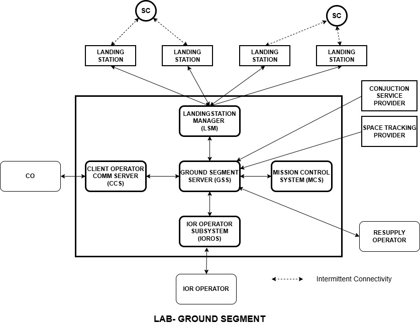
Figure 1 – Ground Segment Logical Architecture
Arrows represent logical information exchanges between GS logical components and external entities. Detailed interface definitions are provided in the subsections below (e.g., GSS ↔ MCS, GSS ↔ LSM) and in 1.8 Boundaries and Interfaces:
1.8 Boundaries and Interfaces
Ground Segment Server (GSS) <->Mission Control System (MCS)
The Mission Control System (MCS) provides planning services for the Ground Segment (GS). It computes three main types of mission plans:
- Contact Plans (CP) – Time-tagged contact windows between Spacecraft (SC) and Landing Stations (LS). These plans are provided to both SC and LS.
- Service Delivery Plans (SDP) – Maneuver and trajectory plans for chaser (SV) to target and phase alignment to enable service delivery to the target the CS.
- Service Plans (SP) – Time-tagged plans describing when and how service will be delivered to the Client Spacecraft. The chaser CV can be very distant from the target CS so the Service Plan provides the optimal time and location for RPOD initiation and delivery of service. The service plan can be schedule many months in advance.
The Ground Segment Server (GSS) orchestrates all GS operations and uses MCS planning services by sending planning requests and receiving the resulting plan.
Interfaces – Remove Verb in the interface name
| SNO | Interface Name | SRC | DST | Parameters | Purpose | Description | Type |
|---|---|---|---|---|---|
| 1 | GenerateInitialAccessPlan | GSS | MCS |
|
Request generation of initial access plan. Initial Access plans are course time based visibility windows for spacecrafts to landing stations communications. These are initial plans used by SCs to communicate with LSs. Access plans are programmed into the SC before launch. |
| 2 | CreateContactPlan | GSS | MCS |
|
Request generation of Contact Plans (CP). Contact plans are time-tagged schedules for the specified spacecraft to communicate with landing stations.
Command / Request |
| 3 | ContactPlanReady | MCS | GSS | • Contact Plans (CP) | Notify GSS that a new set of Contact Plans has been generated. The GSS would then distribute the contact plans to LS and SC.
Event / Response |
| 4 | CreateServiceDeliveryPlans | GSS | MCS |
|
Command / Request | Request generation of Service Delivery Plans (SDP) – maneuver/trajectory plans for target and phase alignment. |
| 5 | ServiceDeliveryPlansReady | MCS | GSS | • Service Delivery Plans (SDP) | Event / Response | Notify GSS that a new set of Service Delivery Plans has been generated and is ready for downstream use. |
| 6 | CreateServicePlans | GSS | MCS |
|
Command / Request | Request generation of Service Plans (SP) that describe optimized service delivery timelines to the Client Spacecraft. |
| 7 | ServicePlansReady | MCS | GSS | • Service Plans (SP) | Event / Response | Notify GSS that a new set of Service Plans has been generated and is ready for downstream use (e.g., to CO, LS, SC as needed). |
Notes:
- Detailed data definitions for Ephemeris, Keplerian Elements, and planning products (CP, SDP, SP) are provided in 1.8 Boundaries and Interfaces
- This subsection captures the logical GSS ↔ MCS exchanges. Physical realization (deployment, protocols) is defined in 1.7 Physical Architecture
Ground Segment Server (GSS) ↔ Landing Station Manager (LSM)
The Landing Station Manager (LSM) distributes Contact Plans to Landing Stations (LS) and to Spacecraft (SC) through the Landing Stations. Landing Stations are 3rd‑party ground assets distributed globally that, using the Contact Plans, enable communications between the Spacecraft and the Ground Segment (GS).
Interfaces
| SNO | Interface Name | SRC | DST | Parameters | Type | Purpose |
|---|---|---|---|---|---|
| 1 | ConfigureLandingStation | GSS | LSM | Command: Add, Delete, Update, Read | Command | GSS coordinates with LSM all the LS the GS uses. |
| 2 | DistributeContactPlans | GSS | LSM | ContactPlan | Command | Distribute the Contact Plans to the LS and SCs |
| 3 | ContactPlanDistributionStatus | LSM | GSS | Status: {Distributed, Partial, Failed} | Status| Sends the status of DistributeContactPlans request. |
| 4 | LandingStationStatus | LSM | GSM |
|
LSM sends individual LandingStationStatus as LS are updated with latest contact plans. |
Landing Station Manager (LSM) ↔︎ Spacecraft (SC)
Spacecraft section covers messages which are common to any IOR Cooperative spacecraft. These are Service Vehicle, Depot and Resupply vehicle. In case Client Spacecraft (CS) is IOR cooperative SC would also cover the CS
LSM Distributes the both HSL and LSL Contact Plans to each Spacecraft. LSM maintains communications with each SC to distribute these plans.
| SNO | Interface Name | SRC | DST | Parameters | Purpose/Type |
|---|---|---|---|---|---|
| 1 | ContactPlanUpdate | LSM | SC | Contact Plan ID
Contact Plan LinkType {HSL, LSL} |
Contact Plan windows to SC
Type: Data |
| 2 | ContactPlanAck | SC | LSM | Contact Plan ID
ReturnCode {Received, Error } |
Type: Status |
Ground Segment Server (GSS)↔︎ Spacecraft (SC)
Ground Segment Server and SC talk through the Landing Station (as per the active contact window), Terrestrial Network and to the GSS. Spacecraft can either be a Depot or a Service Vehicle.
| SNO | Interface Name | SRC | DST | Parameters | Purpose/Type |
|---|---|---|---|---|---|
| 1 | SCOrbitalStatus | SC | GSS |
|
Sent Autonomously
Type: Status |
| 2 | SCTelemetryData | SC | GSS |
|
Sent Autonomously
Type: Data |
| 3 | SCEphemerisData | SC | GSS |
|
Sent Autonomously
Type: Data |
Ground Segment Server (GSS) <-> Service Vehicle
This interface is an external interface between IOR GS and SV and is covered in 1.8 Boundaries and Interfaces
Ground Segment Server (GSS) <-> Depot
This interface is an external interface and is covered in 1.8 Boundaries and Interfaces
IOR Spacecraft
IOR spacecraft is available in 4 capability levels as outlined here and with capability requirements here. Following sections provides details of the 4 capability levels:
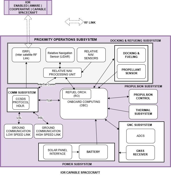
IOR Capable Spacecraft
IOR capable spacecrafts have the ability to be master or slave in the service delivery and RPOD process. SV (chaser, master), Depot (target, slave), Resupply Vehicle (chaser, master) and IOR capable client spacecraft (target, slave) are IOR capable space crafts. IOR capable spacecraft logical architecture decomposition and inter-component interfaces are defined in this section
IOR Cooperative Spacecraft
├── Proximity Operations Subsystem
│ ├── SRFL (Inter-satellite RF Link)
│ ├── Relative Navigation Sensor (LiDAR)
│ ├── Relative Navigation Sensors
│ └── Relative Navigation Processing Unit
│
├── GNC Subsystem
│ ├── ADCS
│ └── GNSS Receiver
│
├── Propulsion Subsystem
│ ├── Propulsion Control
│ └── Thermal Subsystem
│
├── Docking & Refueling Subsystem
│ ├── Docking & Fueling
│ └── Propellant Sensor
│
├── Communication Subsystem
│ ├── CCSDS Protocol Handler
│ ├── Ground Communication Low Speed Link (LSL)
│ └── Ground Communication High Speed Link (HSL)
│
├── Power Subsystem
│ ├── Solar Panel Interface
│ └── Battery
│
└── Onboard Computing (OBC)
└── Refuel Orchestrator (RO)
ReFuel Orchestrator (RFO)↔︎ Proximity Operations Subsystem (POS)
Interface Type: 2 Way communication.
| SNO | Interface Name | SRC | DST | Parameters | Type | Purpose |
|---|---|---|---|---|---|
| 1 | StartProximitySystem | RFO | POS | None. | Command | Start the proximity system and establish communication. |
| 2 | SpacecraftDetected | POS | RFO | Status | The POS local navigation system detected a remote spacecraft. Communication is not established yet. | |
| 3 | EstablishISRFL | RFO | POS | RF Frequency, CraftID | Command. Send command to attempt to make a two way communication effort with remote craft. |
| 4 | EstablishISRFLStatus | POS | RFO | Status: {Established, Failed} | Status |
| 5 | ProximityOperationInit | RFO | POS |
|
Status. This message is sent to remote craft. |
| 6 | OnProximityOperationInit | POS | RFO |
|
Status. This message is received from remote craft. |
| 7 | ProximityOperationReady | RFO | POS |
|
Status. This message is sent to from remote craft when this craft is ready to start the proximity operations. |
| 8 | Please see this to see rest of the messages between RFO/POS | ||||
ReFuel Orchestrator (RFO)↔︎ GNC
Refuel Orchestrator (RFO) requires services of GNC to accomplish its tasks. RFO:
- Uses GNC to determine attitude of the spacecraft.
- Uses Galileo GNSS to determine the Ephemeris data
- Uses GNC to alter the attitude of the spacecraft
| SNO | Interface Name | SRC | DST | Parameters | Type | Purpose |
|---|---|---|---|---|---|
| 1 | GetAttitude | RFO | GNC | None. | Request | Get spacecraft attitude |
| 2 | GetAttitudeResponse | GNC | RFO | pitch, roll, yaw Angles. | Response |
| 3 | GetEphemeris | RFO | GNC | None | Request| Get the emphemeris of spacecraft |
| 4 | GetEphemerisResponse | GNC | RFO | X, Y, Z, Vx, Vy, Vz | Response |
| 5 | Roll | RFO | GNC | roll Angle | Command |
| 6 | Pitch | RFO | GNC | pitch Angle | Command |
| 7 | Yaw | RFO | GNC | yaw Angle | Command |
ReFuel Orchestrator (RFO)↔︎ PRopulsion System (PRS)
Refuel Orchestrator (RFO) requires services of PRopulsion System (PRS)to accomplish its tasks. RFO:
- Uses PRS to manuever the spacecraft (both in Orbit Phasing stage and during proximity operations)
| SNO | Interface Name | SRC | DST | Parameters | Type | Purpose |
|---|---|---|---|---|---|
| 1 | PerformManeuver | RFO | PRS | ΔV | Command |
| 2 | ManeuverStatus | PRS | RFO | ΔV Achieved
ΔV Residual |
Status |
ReFuel Orchestrator (RFO)↔︎Docking and Refueling System (DRS)
Docking and Refueling System (DRS) is available only in crafts at capability level of: IOR Cooperative. Only client spacecraft may not have the capability level of IOR Cooperative. The Dept, SV and Resupply Vehicle all have capability level of IOR Cooperative.
Refuel Orchestrator (RFO) requires services of Docking and Refueling System (DRS)to accomplish its tasks. RFO:
- Uses DRS to get the docking status
- Uses DRS to dock
- Uses DRS to undock
- Uses DRS to start Refuel (for Master spacecraft which needs to deliver fuel)
- Uses DRS to stop Refuel
- Uses Propellant Sensor to monitor Refuel
These tasks are performed at the edge of the Proximity Operations.
| SNO | Interface Name | SRC | DST | Parameters | Type | Purpose |
|---|---|---|---|---|---|
| 1 | GetDockingStatus | RFO | DRS | None | Command |
| 2 | DockingStatus | DRS | RFO | NOT_DOCKED DOCKED DOCKING |
Response |
| 3 | PerformDock | RFO | DRS | None | As a master, perform the dock. As a slave participate in the dock |
| 4 | PerformUndock | RFO | DRS | None | As a master, perform the undock. As a slave participate in the undock |
| 5 | StartPropellantTransfer | RFO | DRS | None | As a master, start the transfer. This is NOP in a slave. |
| 6 | StopPropellantTransfer | RFO | DRS | None | As a master, stop the transfer. This is NOP in a slave. |
| 7 | GetPropellantLevel | RFO | DRS | None | Request |
| 8 | PropellantLevel | DRS | RFP | propellant Level | Response |
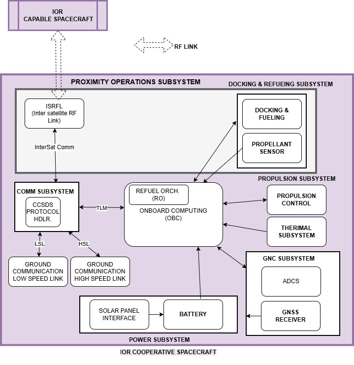
IOR Cooperative Spacecraft
IOR cooperative spacecraft assists the IOR capable space craft in pre-docking, docking, transfer and post dock operations by forming a two way RF communication link. It has a subset of capabilities of an IOR Cooperative spacecraft.
IOR Cooperative spacecraft through the Client Ground Segment assists the ISP GS during the RPOD and propellant transfer process.